1605-A: Difference between revisions
Jump to navigation
Jump to search
No edit summary |
mNo edit summary |
||
| (12 intermediate revisions by 2 users not shown) | |||
| Line 1: | Line 1: | ||
{{GR Product | {{GR Product | ||
|model=1605-A | |model=1605-A | ||
|codes=GUNNY,GIPSY,1605-9801,1605-9811 | |||
|class=impedance measurement | |class=impedance measurement | ||
|summary= | |summary=Impedance comparator | ||
|image=GR 1605-A Front.jpg | |image=GR 1605-A Front.jpg | ||
|caption=General Radio 1605-A Impedance Comparator | |caption=General Radio 1605-A Impedance Comparator | ||
| Line 10: | Line 11: | ||
|designers= | |designers= | ||
|manuals= | |manuals= | ||
* [[Media:GRwiki 1605-A Impedance Comparator | * [[Media:GRwiki 1605-A Impedance Comparator 1605-0100-E 04-1961.pdf|General Radio 1605-A Impedance Comparator Manual 1605-01100-E 1961]] | ||
{{Catalog History}} | |||
}} | }} | ||
The | The {{Title|General Radio 1605-A Impedance Comparator}} was introduced in {{Catalog O}} and remained available through {{Catalog T}}. | ||
The Type 1605-A can be used to compare pairs of components for magnitude and phase difference. It displays the results on separate meters (magnitude, phase). | The Type 1605-A can be used to compare pairs of components for magnitude and phase difference. It displays the results on separate meters (magnitude, phase). | ||
Using the built-in guard circuit during measurement, the unknown can be remotely located during measurement. | Using the built-in guard circuit during measurement, the unknown can be remotely located during measurement. | ||
Some other applications include checking ganged potentiometers or variable capacitors for tracking, checking balances of transformer windings, or adjusting coils to a standard. | Some other applications include checking ganged potentiometers or variable capacitors for tracking, checking balances of transformer windings, or adjusting coils to a standard. | ||
| Line 22: | Line 25: | ||
** Resistance: 2 Ω to 20 MΩ | ** Resistance: 2 Ω to 20 MΩ | ||
** Capacitance: 40 pF to 500 μF | ** Capacitance: 40 pF to 500 μF | ||
** Inductance: | ** Inductance: 20 μH to 10,000 H | ||
* '''Internal Oscillator Frequencies:''' 100 Hz, 1 kHz, 10 kHz, 100 kHz | * '''Internal Oscillator Frequencies:''' 100 Hz, 1 kHz, 10 kHz, 100 kHz | ||
* '''Meter Ranges:''' | * '''Meter Ranges:''' | ||
| Line 30: | Line 33: | ||
==Links== | ==Links== | ||
* [[Media:GR Exp 1605-A 04_1956.pdf|Experimenter April 1956 describing Type 1605-A]] | * [[Media:GR Exp 1605-A 04_1956.pdf|Experimenter April 1956 describing Type 1605-A]] | ||
* Predecessor: [[1604-B|General Radio 1604-B Comparison Bridge]] (1954) | |||
* Successor: [[1654|General Radio 1654 Impedance Comparator]] (1970) | |||
==Photos== | ==Photos== | ||
| Line 39: | Line 43: | ||
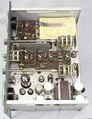
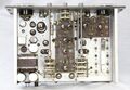
GR 1605-A Top.jpg | GR 1605-A Top.jpg | ||
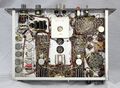
GR 1605-A Bottom.jpg | GR 1605-A Bottom.jpg | ||
GR 1605-P1 Test Jig.jpg|Test Jig | |||
</gallery> | </gallery> | ||
[[Category:Impedance measurement]] | [[Category:Impedance measurement]] | ||
Latest revision as of 15:07, 25 April 2024

The General Radio 1605-A Impedance Comparator was introduced in Catalog O (1956) and remained available through Catalog T (1968).
The Type 1605-A can be used to compare pairs of components for magnitude and phase difference. It displays the results on separate meters (magnitude, phase). Using the built-in guard circuit during measurement, the unknown can be remotely located during measurement.
Some other applications include checking ganged potentiometers or variable capacitors for tracking, checking balances of transformer windings, or adjusting coils to a standard.
Specifications
- Impedance Ranges:
- Resistance: 2 Ω to 20 MΩ
- Capacitance: 40 pF to 500 μF
- Inductance: 20 μH to 10,000 H
- Internal Oscillator Frequencies: 100 Hz, 1 kHz, 10 kHz, 100 kHz
- Meter Ranges:
- Impedance Magnitude Difference: ±0.3%, ± 1%, ±3%, ± 10% full scale
- Phase Angle Difference: ±0.003, ±0.01, ±0.03, ± 0.1 radian full scale
- Voltage Across Standard and Unknown: approx. 0.15 V
Links
- Experimenter April 1956 describing Type 1605-A
- Predecessor: General Radio 1604-B Comparison Bridge (1954)
- Successor: General Radio 1654 Impedance Comparator (1970)
Photos
-

-
-
-
-
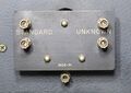
Test Jig


