1650-P1: Difference between revisions
Jump to navigation
Jump to search
(Created page with "Type '''1650-P1 Test Jig'''. ==Specifications== ==Links== ==Photos== <gallery> </gallery> Category:Impedance measurement") |
No edit summary |
||
| Line 1: | Line 1: | ||
{{GR Product | |||
|model=1650-P1 | |||
|class=impedance measurement | |||
|summary=Test jig | |||
|image=GR 1650-P1 Close-up.jpg | |||
|caption=General Radio | |||
|series=1650 | |||
|introduced=1959 | |||
|discontinued=1978+ | |||
|designers= | |||
|manuals= | |||
* '''Manual Needed''' | |||
{{Catalog History}} | |||
}} | |||
The {{Title|General Radio 1650-P1 Test Jig}} was introduced in {{Catalog P}} and remained available through {{Catalog 1978}}. | |||
The Type 1650-P1 Test Jig is an accessory designed for the [[1650-A]] but usefull with any instrument that accepts | |||
the Type [[274-NK]] double plug. It provides a three terminal connection to the measuring device, two shielded ungrounded terminals to the unknown and ground. The terminals of the Test Jig provide a rapid way to connect axial lead components for testing and sorting. | |||
==Specifications== | ==Specifications== | ||
* '''Lead Resistance:''' 0.08 Ω total | |||
* '''Inductance Q Error:''' D (or 1/Q) of less than 0.007 | |||
==Links== | ==Links== | ||
* [[Media:GR Exp 1650-P1 03_1959.pdf|Experimenter describing Type 1650-P1 March 1959]] | |||
==Photos== | ==Photos== | ||
<gallery> | <gallery> | ||
GR 1650-P1 Front.jpg | |||
GR 1650-P1 Left.jpg | |||
GR 1650-P1 Rear.jpg | |||
GR 1650-P1 Right.jpg | |||
GR 1650-P1 Bottom.jpg | |||
</gallery> | </gallery> | ||
[[Category:Impedance measurement]] | [[Category:Impedance measurement]] | ||
Revision as of 05:39, 24 April 2024
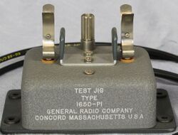
The General Radio 1650-P1 Test Jig was introduced in Catalog P (1959) and remained available through Catalog 1978.
The Type 1650-P1 Test Jig is an accessory designed for the 1650-A but usefull with any instrument that accepts the Type 274-NK double plug. It provides a three terminal connection to the measuring device, two shielded ungrounded terminals to the unknown and ground. The terminals of the Test Jig provide a rapid way to connect axial lead components for testing and sorting.
Specifications
- Lead Resistance: 0.08 Ω total
- Inductance Q Error: D (or 1/Q) of less than 0.007


