1482-A: Difference between revisions
No edit summary |
No edit summary |
||
| Line 27: | Line 27: | ||
* '''DC Resistance:''' 0.039 Ω | * '''DC Resistance:''' 0.039 Ω | ||
* '''Q at 100 Hz:''' 0.81 | * '''Q at 100 Hz:''' 0.81 | ||
* ''' | * '''Current rms:''' 2.26 A, 1.5° C rise, 200 mW; 8.77 A, 20° C rise, 3 W | ||
* '''Stability:''' inductance change is less than ±0.01% per year | * '''Stability:''' inductance change is less than ±0.01% per year | ||
==Links== | ==Links== | ||
* [[Media:GR Exp 1482 11_1952.pdf|Experimenter | * [[Media:GR Exp 1482 11_1952.pdf|Experimenter November 1952 describing Type 1482 Series]] | ||
==Photos== | ==Photos== | ||
Latest revision as of 02:41, 1 August 2024
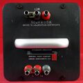
The General Radio 1482-A Standard Inductor was introduced in Catalog Q (1961) and remained available through Catalog U (1970).
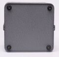
The Type 1482-A is 50 μH inductance standard designed to replace the Type 106 Standard Inductor. The inductor is symmetrically wound toroid on a ceramic core. The toroid is hermetically sealed in a mixture of cork and silica gel then potted in an aluminum case. The connections to the inductor are three Type 938-A jack-top binding posts. Two of the terminals for the inductor and the third is the case connection with shorting link, affording two or three terminal standards. Each inductor is supplied with a calibration certificate with corrections for 200 Hz, 500 Hz, and 1 kHz and actual specifications.
For all the members of the series see 1482 article.
Specifications
- Nominal Inductance: 50 μH
- Accuracy: ±0.5%
- Resonant Frequency: 3.1 MHz
- DC Resistance: 0.039 Ω
- Q at 100 Hz: 0.81
- Current rms: 2.26 A, 1.5° C rise, 200 mW; 8.77 A, 20° C rise, 3 W
- Stability: inductance change is less than ±0.01% per year


