975: Difference between revisions
Jump to navigation
Jump to search
(Created page with "Type '''975 Series Potentiometers'''. ==Specifications== ==Links== ==Photos== <gallery> </gallery> Category:Resistance Standards") |
|||
| (5 intermediate revisions by the same user not shown) | |||
| Line 1: | Line 1: | ||
Type ' | {{GR Product | ||
|model=975 | |||
|codes= | |||
|class=Resistance Standards | |||
|summary=Potentiometer Series | |||
|image=GR 975-J 500 ohms.jpg | |||
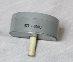
|caption=General Radio 975 Potentiometer Series | |||
|series=975 | |||
|introduced=1956 | |||
|discontinued=1973 | |||
|designers= | |||
|manuals= | |||
* [[Media:GR 970 Potentiometer Series Instruction Sheet 0970-0100-L 08_1965.pdf|General Radio 970 Series Instruction Sheet 0970-0100-L 1965]] | |||
{{Catalog History}} | |||
}} | |||
The {{Title|General Radio 975 Potentiometer Series}} was introduced in {{Catalog O}} and remained available through {{Catalog 1973}}. | |||
The Type 975 is part of the [[970]] Series of general purpose potentiometers. They are useful for dc, throughout the audio and ultrasonic-frequency ranges. They have the ability to be stacked while using a common ⅜ inch shaft. Stacking requires hardware that's not included. Mounting is by three 6-32 supplied screws. The basic power rating for the Type 975 is 10 watts. The 975 Series replaced the Type [[214-A]] Series of potentiometers. The recommended dial plate is the Type [[970-P2]]. | |||
==Specifications== | ==Specifications== | ||
* '''Effective Electrical Rotation:''' 320° ±2° | |||
* '''Total Mechanical Rotation:''' 330° ± 5° | |||
* '''Average Torque:''' 4 oz/in. | |||
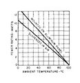
* '''Power Rating:''' panel mounted 13.4 w, suspended in air 10.7 w, see the power rating chart below | |||
{| class="wikitable" style="margin:auto" | |||
|+ Type 975 Series of Potentiometers | |||
|- | |||
! Type!! Resistance !! Temperature<br>Coefficient !!Resolution !! Independant<br>Linearity !!Code | |||
|- | |||
|#[[975-D]] || 10 Ω || +0.07% || <0.5% ||±1% || | |||
|- | |||
|#[[975-E]] || 20 Ω || +0.07% || <0.5% ||±1% || | |||
|- | |||
|#[[975-F]] || 50 Ω || ±0.002% || <0.5% ||±1% || | |||
|- | |||
|#[[975-G]] || 100 Ω || ±0.002% || <0.5% ||±1% || | |||
|- | |||
|#[[975-H]] || 200 Ω || ±0.002% || <0.5% ||±1% || | |||
|- | |||
|[[975-J]] || 500 Ω || ±0.002% || <0.2% ||±0.5% || 0975·9710 | |||
|- | |||
|[[975-K]] || 1000 Ω || ±0.002% || <0.2% ||±0.5% || 0975·9711 | |||
|- | |||
|[[975-L]] || 2000 Ω || ±0.002% || <0.2% ||±0.5% || 0975·9712 | |||
|- | |||
|[[975-M]] || 5000 Ω || ±0.002% || <0.2% ||±0.5% || 0975·9713 | |||
|- | |||
|[[975-N]] || 10 kΩ || ±0.002% || <0.1% ||±0.5% || 0975·9714 | |||
|- | |||
|[[975-P]] || 20 kΩ || ±0.002% || <0.1% ||±0.5% || 0975·9716 | |||
|- | |||
|[[975-Q]] || 50 KΩ || +0.002% || <0.05% ||±0.5% || 0975·9717 | |||
|- | |||
|[[975-R]] || 100 KΩ || +0.002% || <0.05% ||±0.5% || 0975·9718 | |||
|- | |||
|} | |||
* '''# Available by request''' | |||
==Links== | ==Links== | ||
* [[Media:GR Exp 970 Series 01_1955.pdf|Experimenter January 1955 describing Type 970 Series]] | |||
==Photos== | ==Photos== | ||
<gallery> | <gallery> | ||
GR 975-J 500 ohms.jpg | |||
GR 975 Top.jpg | |||
GR 975 Front.jpg | |||
GR 975 Open.jpg | |||
GR 975 Mechanical Drawing.jpg|Mechanical Drawing | |||
GR 975 Power Rating Chart.jpg|Power Rating Chart | |||
</gallery> | </gallery> | ||
[[Category:Resistance Standards]] | [[Category:Resistance Standards]] | ||
Latest revision as of 07:42, 17 July 2024
The General Radio 975 Potentiometer Series was introduced in Catalog O (1956) and remained available through Catalog 1973.
The Type 975 is part of the 970 Series of general purpose potentiometers. They are useful for dc, throughout the audio and ultrasonic-frequency ranges. They have the ability to be stacked while using a common ⅜ inch shaft. Stacking requires hardware that's not included. Mounting is by three 6-32 supplied screws. The basic power rating for the Type 975 is 10 watts. The 975 Series replaced the Type 214-A Series of potentiometers. The recommended dial plate is the Type 970-P2.
Specifications
- Effective Electrical Rotation: 320° ±2°
- Total Mechanical Rotation: 330° ± 5°
- Average Torque: 4 oz/in.
- Power Rating: panel mounted 13.4 w, suspended in air 10.7 w, see the power rating chart below
| Type | Resistance | Temperature Coefficient |
Resolution | Independant Linearity |
Code |
|---|---|---|---|---|---|
| #975-D | 10 Ω | +0.07% | <0.5% | ±1% | |
| #975-E | 20 Ω | +0.07% | <0.5% | ±1% | |
| #975-F | 50 Ω | ±0.002% | <0.5% | ±1% | |
| #975-G | 100 Ω | ±0.002% | <0.5% | ±1% | |
| #975-H | 200 Ω | ±0.002% | <0.5% | ±1% | |
| 975-J | 500 Ω | ±0.002% | <0.2% | ±0.5% | 0975·9710 |
| 975-K | 1000 Ω | ±0.002% | <0.2% | ±0.5% | 0975·9711 |
| 975-L | 2000 Ω | ±0.002% | <0.2% | ±0.5% | 0975·9712 |
| 975-M | 5000 Ω | ±0.002% | <0.2% | ±0.5% | 0975·9713 |
| 975-N | 10 kΩ | ±0.002% | <0.1% | ±0.5% | 0975·9714 |
| 975-P | 20 kΩ | ±0.002% | <0.1% | ±0.5% | 0975·9716 |
| 975-Q | 50 KΩ | +0.002% | <0.05% | ±0.5% | 0975·9717 |
| 975-R | 100 KΩ | +0.002% | <0.05% | ±0.5% | 0975·9718 |
- # Available by request
Links
Photos
-
-
-
-
-
Mechanical Drawing
-
Power Rating Chart
