1409: Difference between revisions
(→Photos) |
|||
| (5 intermediate revisions by the same user not shown) | |||
| Line 73: | Line 73: | ||
===Small Case=== | ===Small Case=== | ||
<gallery> | <gallery> | ||
GR 1409 Small Case Front.jpg | |||
GR 1409 Small Case Left.jpg| Thermometer Access | |||
GR 1409 Small Case Right.jpg | |||
GR 1409 Small Case Top.jpg | |||
GR 1409 Small Case Bottom.jpg | |||
GR 1409 Small Case Back.jpg | |||
</gallery> | </gallery> | ||
===Medium Case=== | ===Medium Case=== | ||
<gallery> | <gallery> | ||
GR 1409-X Front.jpg | |||
GR 1409-X Terminal Medium Case.jpg | |||
GR 1409-X Bottom Medium Case.jpg | |||
</gallery> | </gallery> | ||
===Large Case=== | ===Large Case=== | ||
<gallery> | <gallery> | ||
GR 1409-Y Front A.jpg | |||
GR 1409-Y Rear Large Case.jpg | |||
</gallery> | </gallery> | ||
Latest revision as of 01:24, 12 July 2024
The General Radio General Radio 1409 Standard Capacitor was introduced in Catalog O (1956) and remained available through Catalog 1978.
The 1409 Standard Capacitors are fixed mica capacitors of very high stability for use as two or three-terminal capacitance standards in the laboratory. The capacitor is installed in an aluminum case along with Silica gel desiccant then sealed with hi-temp potting wax. A well located on the right side of the case for the insertion of a dial-type thermometer. Three jack-top binding posts are provided on the top of the case and removable plugs on the bottom, for convenient parallel connection without error. Each capacitor is supplied with a certificate of calibration giving two and three terminal measured capacitance.
Specifications
- Adjustment Accuracy: within ±0.05%
- Stability: capacitance change is less than 0.01% per year
- Temperature Coefficient: capacitance, +35 ± 10 ppm per degree between 10 °C and 70 °C
- Dissipation Factor: less than 0.0003 at 1 kHz and 23 °C (see curves). Measured dissipation factor at 1 kHz is stated in the certificate to an accuracy of ±0.00005
- Leakage Resistance: 5000 ohm-farads or 100 GΩ, whichever is the lesser
- Maximum Voltage: 500 V peak below the limiting frequencies tabulated below
Links
| Type | Capacitance | Frequency Limit for Max Volts |
Series Inductance | Code Number |
|---|---|---|---|---|
| 1409-F | 0.001 μF | 4.7 MHz | 0.050 μH | 1409-9702 |
| 1409-G | 0.002 μF | 2.7 MHz | 0.050 μH | 1409-9707 |
| 1409-K | 0.005 μF | 1.3 MHz | 0.050 μH | 1409-9711 |
| 1409-L | 0.01 μF | 750 kHz | 0.050 μH | 1409-9712 |
| 1409-M | 0.02 μF | 430 kHz | 0.050 μH | 1409-9713 |
| 1409-R | 0.05 μF | 210 kHz | 0.055 μH | 1409-9718 |
| 1409-T | 0.1 μF | 120 kHz | 0.055 μH | 1409-9720 |
| 1409-U | 0.2 μF | 70 kHz | 0.055 μH | 1409-9721 |
| #1409-X | 0.5 μF | 35 kHz | 0.055 μH | 1409-9724 |
| ##1409-Y | 1 μF | 17 kHz | 0.070 μH | 1409-9725 |
- # Mounted in medium case.
- ## Mounted in large case.
Photos
-
Change in capacitance as a function of frequency for typical Type 1409 capacitors.
-
Dissipation factor as a function of frequency.
-
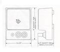
Technical Drawing.
Small Case
-
-
Thermometer Access
-
-
-
-
Medium Case
Large Case


