874-MR: Difference between revisions
No edit summary |
No edit summary |
||
| (4 intermediate revisions by 2 users not shown) | |||
| Line 6: | Line 6: | ||
|image=GR 874-MR Close-Up.jpg | |image=GR 874-MR Close-Up.jpg | ||
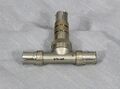
|caption=General Radio 874-MR Mixer Rectifier | |caption=General Radio 874-MR Mixer Rectifier | ||
|series=874 | |series=GR-874 | ||
|introduced=1951 | |introduced=1951 | ||
|discontinued=1973 | |discontinued=1973 | ||
|designers= | |designers= | ||
|manuals= | |manuals= | ||
* | * [[Media:GR 874-MR Mixer Rectifier 0874-0337-H 10-1962.pdf|General Radio 874-MR Mixer Rectifier Manual 0874-0337-H 10-1962]] | ||
{{Catalog History}} | {{Catalog History}} | ||
}} | }} | ||
The {{Title|General Radio 874-MR Mixer Rectifier}} was introduced in {{Catalog M}} and remained available through {{Catalog 1973}}. | The {{Title|General Radio 874-MR Mixer Rectifier}} was introduced in {{Catalog M}} and remained available through {{Catalog 1973}}, after which only the [[874-MRL]] version with locking connectors remained available. | ||
The Type 874-MR is a device used to mix two signals, the input signal and a local oscillator, to produce an intermediate frequency. The range of both input and local oscillator is | The Type 874-MR is a device used to mix two signals, the input signal and a local oscillator, to produce an intermediate frequency. The range of both input and local oscillator is 40 to 5000 MHz, and the intermediate frequency range is up to 30 MHz. | ||
Tge 874-MR enables UHF signals to be monitored conveniently by radio receivers, wide-band amplifiers or null detectors operating at the IF frequency. | |||
The output signal from the 874-MR passes through a 1N21 diode followed by a low-pass pi filter. | |||
Maximum input from the local oscillator must be kept below 2 V to prevent damage to the 1N21 rectifier. | |||
==Specifications== | ==Specifications== | ||
* '''Operating Frequency:''' | * '''Operating Frequency:''' 40 to 5000 MHz | ||
* '''Maximum Crystal Current:''' 5 mA | * '''Maximum Crystal Current:''' 5 mA | ||
* '''Maximum Input from Local Oscillator:''' 2 V | * '''Maximum Input from Local Oscillator:''' 2 V | ||
* '''Cut-Off Frequency of Output | * '''Cut-Off Frequency of Output Filter:''' 40 MHz | ||
==Links== | ==Links== | ||
| Line 36: | Line 42: | ||
GR 874-MR Open.jpg | GR 874-MR Open.jpg | ||
GR 874-MR Apart.jpg | GR 874-MR Apart.jpg | ||
GR 874-MR 1N21B.jpg | GR 874-MR 1N21B.jpg|1N21B Diode | ||
GR 874-VR Schematic.jpg | GR 874-VR Schematic.jpg|Schematic | ||
</gallery> | </gallery> | ||
[[Category:Coaxial Elements]] | [[Category:Coaxial Elements]] | ||
[[Category:GR-874]] | [[Category:GR-874]] | ||
Latest revision as of 01:26, 1 July 2024

The General Radio 874-MR Mixer Rectifier was introduced in Catalog M (1951) and remained available through Catalog 1973, after which only the 874-MRL version with locking connectors remained available.
The Type 874-MR is a device used to mix two signals, the input signal and a local oscillator, to produce an intermediate frequency. The range of both input and local oscillator is 40 to 5000 MHz, and the intermediate frequency range is up to 30 MHz.
Tge 874-MR enables UHF signals to be monitored conveniently by radio receivers, wide-band amplifiers or null detectors operating at the IF frequency.
The output signal from the 874-MR passes through a 1N21 diode followed by a low-pass pi filter.
Maximum input from the local oscillator must be kept below 2 V to prevent damage to the 1N21 rectifier.
Specifications
- Operating Frequency: 40 to 5000 MHz
- Maximum Crystal Current: 5 mA
- Maximum Input from Local Oscillator: 2 V
- Cut-Off Frequency of Output Filter: 40 MHz
Links
Photos
-
-

-

-

-

-
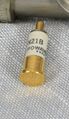
1N21B Diode
-

Schematic


