1658: Difference between revisions
(Created page with "Type '''1658 RLC Digibridge'''. ==Specifications== ==Links== ==Photos== <gallery> </gallery> Category:Impedance measurement") |
No edit summary |
||
| (6 intermediate revisions by 2 users not shown) | |||
| Line 1: | Line 1: | ||
Type | {{GR Product | ||
|model=1658 | |||
|codes=1658-9700 | |||
|class=impedance measurement | |||
|summary=RLC Digibridge | |||
|image=GR 1658 Close-Up.jpg | |||
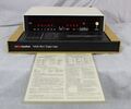
|caption=General Radio 1658 RLC Digibridge | |||
|series=1685 | |||
|introduced=1978 | |||
|discontinued=1978+ | |||
|designers= | |||
|manuals= | |||
* [[Media:GR 1658 RCL Digibridge 1658-0120-D 05_1980.pdf|General Radio 1658 RLC Digibridge Manual 1658-0120-D 1980]] | |||
* [[Media:GR 1658 Operation Reference Information.pdf|General Radio 1658 Quick Reference Card 1658-0110-A]] | |||
{{Catalog History}} | |||
}} | |||
The {{Title|General Radio 1658 RLC Digibridge}} was available in {{Catalog 1978}} only. | |||
The Type 1658 Digibridge is a digital impedance meter and comparator utilizing microprocessor control. Basic accuracy is 0.1% using a five digit display for RLC, and four digits for D/Q. | |||
It features a built-in test fixture with the option for an extension cable. Measurements can be made at 120 Hz or 1 kHz, and series or parallel circuits are keyboard selectable. | |||
An optional IEEE 488 bus/handler interface is available. The 1658 is equipped with a comparator function for Go/No-Go testing and sorting of components into logical "Bins". | |||
Limits and sorting information is entered using the keyboard. Using this function, it is possible to sort parts by percentage or value. | |||
The measurements are made by the quadrature sampling method, where the standard and the unknown are in series and a sine wave is applied. | |||
Four voltage measurements are taken across the standard and then the unknown at four different phases of the sine wave. | |||
Using their magnitude and phase difference, the processor calculates the results. | |||
It is interesting to note the 1658 uses three measurement rates. The slow rate takes five measurements, medium rate takes eight (Quadrature), and the high rate takes sixteen. | |||
Because the processor creates the test sine wave using a digital-to-analog converter, it has exact phase information for its measurements and calculations, eliminating the need for calibration. | |||
==Specifications== | ==Specifications== | ||
* '''Measurement Ranges''' | |||
* '''Resistance:''' 0.0001 Ω to 9.9999 MΩ at 1 kHz, 0.0001 Ω to 99.999 MΩ at 120 Hz | |||
* '''Inductance:''' .00001 mH to 999.99 H at 1 kHz, 0.0001 mH to 9999.9 H at 120 Hz | |||
* '''Capacitance:''' .00001 nF to 999.99 μF at 1 kHz, 0.0001 nF to 99999 μF at 120 Hz | |||
* '''Dissipation Factor:''' .0001 to 9.999 | |||
* '''Q Factor:''' 00.01 to 999.9 for L/Q, .0001 to 9.999 for R/Q | |||
* '''Basic Accuracy:''' 0.1% | |||
* '''Test Frequencies:''' 120 Hz and 1 kHz | |||
==Links== | ==Links== | ||
* See also [[1657|1657 Digibridge]] | |||
==Photos== | ==Photos== | ||
<gallery> | <gallery> | ||
GR 1658 Front A.jpg | |||
GR 1658 Front.jpg | |||
GR 1658 Left.jpg | |||
GR 1658 Rear.jpg | |||
GR 1658 Right.jpg | |||
GR 1658 Top wo_Cover.jpg | |||
GR 1658 Top wo_PS and Display.jpg | |||
GR 1658 Power Supply Top.jpg | |||
GR 1658 Power Supply Close-Up.jpg | |||
GR 1658 Display Board Component Side.jpg | |||
GR 1658 Main Board Foil Side.jpg | |||
GR 1658 Display Board Component Side B.jpg | |||
GR 1658 Display Board Foil Side.jpg | |||
GR 1658 Keypad.jpg | |||
GR 1658 Operation Reference Information Color.jpg | |||
GR 1658 83K Ohm Measurement.jpg | |||
GR 1658 570pf Measurement.jpg | |||
</gallery> | </gallery> | ||
[[Category:Impedance measurement]] | [[Category:Impedance measurement]] | ||
Latest revision as of 20:00, 12 June 2024
The General Radio 1658 RLC Digibridge was available in Catalog 1978 only.
The Type 1658 Digibridge is a digital impedance meter and comparator utilizing microprocessor control. Basic accuracy is 0.1% using a five digit display for RLC, and four digits for D/Q. It features a built-in test fixture with the option for an extension cable. Measurements can be made at 120 Hz or 1 kHz, and series or parallel circuits are keyboard selectable. An optional IEEE 488 bus/handler interface is available. The 1658 is equipped with a comparator function for Go/No-Go testing and sorting of components into logical "Bins". Limits and sorting information is entered using the keyboard. Using this function, it is possible to sort parts by percentage or value.
The measurements are made by the quadrature sampling method, where the standard and the unknown are in series and a sine wave is applied. Four voltage measurements are taken across the standard and then the unknown at four different phases of the sine wave. Using their magnitude and phase difference, the processor calculates the results. It is interesting to note the 1658 uses three measurement rates. The slow rate takes five measurements, medium rate takes eight (Quadrature), and the high rate takes sixteen. Because the processor creates the test sine wave using a digital-to-analog converter, it has exact phase information for its measurements and calculations, eliminating the need for calibration.
Specifications
- Measurement Ranges
- Resistance: 0.0001 Ω to 9.9999 MΩ at 1 kHz, 0.0001 Ω to 99.999 MΩ at 120 Hz
- Inductance: .00001 mH to 999.99 H at 1 kHz, 0.0001 mH to 9999.9 H at 120 Hz
- Capacitance: .00001 nF to 999.99 μF at 1 kHz, 0.0001 nF to 99999 μF at 120 Hz
- Dissipation Factor: .0001 to 9.999
- Q Factor: 00.01 to 999.9 for L/Q, .0001 to 9.999 for R/Q
- Basic Accuracy: 0.1%
- Test Frequencies: 120 Hz and 1 kHz
Links
- See also 1657 Digibridge


